Motor drive controller boards are the backbone of motion control in robotics, CNC machines, automation projects, and DIY electronics builds. They translate low-level control signals into precise movement, managing speed, direction, and torque across a wide range of motors. The most dependable boards combine efficient power handling, robust protection features, and flexible control options that make them suitable for both experimentation and real-world applications.
Motor Driver Kit with Dual RZ7899 Chips (4 DC Motors)

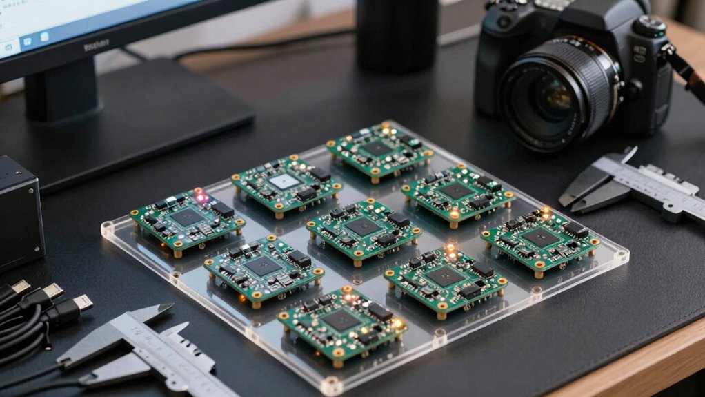
This Motor Driver Kit with Dual RZ7899 Chips (4 DC Motors) is ideal if you need compact, efficient motor control for small robotics projects. You learn what comes in the kit: the board with dual RZ7899 chips, 4 DC motors, and PH2.0 to Dupont cables. You assess compatibility with Arduino, Raspberry Pi, or ESP32, then plan wiring using the PH2.0 connectors or screw terminals. You can control four motors from a single board, saving space. Follow steps: connect power, attach control signals, test each motor, adjust IO timing, and verify heat remains low during use.
Stepper Motor Driver Controller for NEMA 17/23 Motors
https://m.media-amazon.com/images/I/61mIyMXilFL._SX522_.jpg
If you’re building a project that needs precise, real-time control of small steppers, a Stepper Motor Driver Controller for NEMA 17/23 motors is the best choice because it combines a built-in controller, driver, and user interface in one package. It drives NEMA 17/23 motors via forward/reverse and speed/angle control, and it uses a UART for external control. Choose among 4 modes: built-in, external button, external driver, or UART. Use 9 workflow programs like Forward, Reverse, or Loop. The HD LCD shows speed and timing; settings are memory-backed for power-on persistence. External control is compatible with additional drivers.
4 Pack L298N Motor Drive Controller Board Set
https://m.media-amazon.com/images/I/61hWXL5XNNL._AC_SX679_.jpg
Consider the 4 Pack L298N Motor Drive Controller Board Set if you need a ready-to-deploy, multi-channel solution that works with Arduino boards like the UNO R3 and Mega. You set up this pack by noting its DC dual H-bridge and built-in 78M05 stabilizer. If your driving voltage stays under 12V, use the onboard logic; if above 12V, supply an external 5V logic circuit. Verify compatibility with Arduino UNO MEGA R3 and Mega2560, then connect motors and power. Check for strong driving, low heat, and anti-interference features, and follow current and diode protection using the filter capacitor.
KeeYees L298N Motor Driver for Arduino Projects
https://m.media-amazon.com/images/I/71btu5f97fL._AC_SX679_.jpg
The KeeYees L298N Motor Driver stands out for Arduino projects that need dual H-bridges and a wide voltage range. You connect the board to a 5–35V supply and use the two H-bridges to control independent motors. The module supports 0–36 mA logic current and 5V logic, so ensure your logic line matches. If driving voltage exceeds 12V, supply external 5V logic. Use the onboard 5V option for 7–12V inputs, but don’t feed 5V at the 5V input when this is active. Includes four wheels, four DC motors, and jumper wires for quick assembly. Verify compatibility with your Arduino project and test gradual current changes.
L298N Motor Driver Board for Arduino
https://m.media-amazon.com/images/I/61VkNn0PcaL._AC_SX679_.jpg
The L298N Motor Drive Controller Board is a solid option when you need to power two DC motors or a two-stepper setup on an Arduino project. You can drive one 2-phase or one 4-phase stepper, or two DC motors with this board. It supports up to 35V and 3A max current, with 2A continuous current. Use a separate 5V logic supply if your drive voltage exceeds 12V to protect the chip. Add large-capacity filter capacitors and a freewheeling diode for stability. The board weighs about 0.88 ounces and fits compact projects. Consider MK-050, ABS body, and 25W rating.
DIANN 2 Sets DC Gearbox Motor with L298N Controller
https://m.media-amazon.com/images/I/71-y3zuVPEL._SX522_.jpg
DIANN 2 Sets DC Gearbox Motor with L298N Controller stands out for beginners needing a complete, ready-to-run package. You’ll receive two TT motors, two wheels, and one L298N controller board. Use 3–6V for the motors, with a 1:48 gear reduction and a 200 RPM free-running speed. Connect to a breadboard or terminal blocks with the 200 mm wiring and 0.1” connectors. Follow safe wiring: use an external 5V logic supply if your drive voltage exceeds 12V. This kit targets DIY cars, smart robots, and small projects, delivering durable motors and a reliable driver for immediate testing.
2 Pack 400W Hall-Effect Brushless DC Motor Driver
https://m.media-amazon.com/images/I/718hrLoR1rL._SX522_.jpg
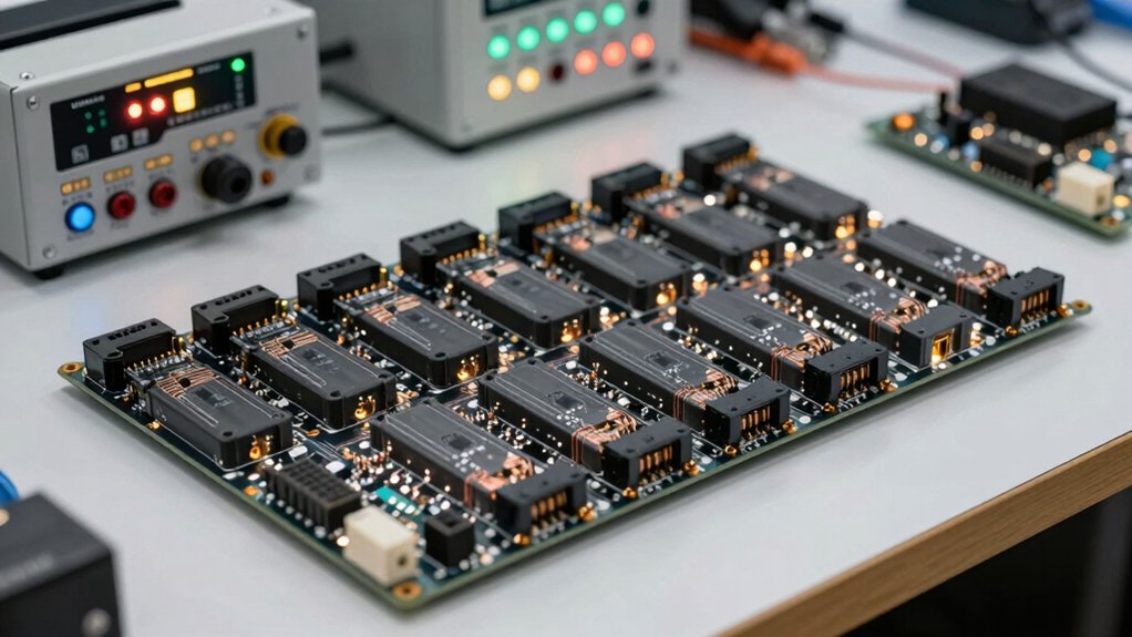
Pack 400W Hall-Effect Brushless DC Motor Driver is a strong choice when you need reliable, high-power control for heavy-duty projects. You connect two 400W brushless units with Hall sensors, building a compact dual-motor drive. Use 6-60V DC inputs to power both boards, then wire each to its motor and hall sensor feedback. Follow the included diagrams for correct polarity and grounding. Do not exceed voltage or current limits to avoid damage. Reversing polarity can permanently harm chips. Verify each connection, test idle before full load, and monitor heat. This setup suits large machinery or equipment needing smooth, precise control.
Factors to Consider When Choosing Motor Drive Controller Boards
First, compare the voltage and current ranges to match your motor’s needs, and confirm your supply can handle peak loads; check whether the board supports the exact motor voltage you plan to use and if current limits are adjustable. Next, verify driver chip compatibility with your motor type and control signals, ensuring you can use your preferred microcontroller and communication interfaces. Finally, assess wiring, connectors, heat dissipation, and supported motor types, and pick a board with solid wiring options, robust heat management, and broad motor compatibility for reliable operation.
Voltage and Current Range
Voltage and current range determine how well a motor drive controller board fits your hardware. You start by checking the supply voltage the board accepts, typically 5–36V or 6–60V, and note if higher voltages require a separate 5V logic supply to protect the onboard regulator. Next, verify the continuous current rating per bridge, commonly 2A–3A, to ensure it matches your motor’s no-load to stall current without overheating. Then assess peak or surge current, which handles startup and transients; confirm the driver can handle brief spikes without triggering protection. Compare motor current needs to the driver’s current limit, and adjust if necessary to prevent overheating. Finally, ensure compatibility across your motor, control logic, and planned voltage range for stable operation.
Driver Chip Compatibility
When selecting a driver chip, you need to match it to your motor type and control needs. First, choose a driver that fits your motor type (DC, stepper, or brushless) and supports the required phase count and current ratings for reliable operation. Next, verify the driver’s peak and continuous current ratings align with your motor load to prevent overheating and voltage drop issues. Then confirm compatibility with your microcontroller platform (Arduino, Raspberry Pi, ESP32) and ensure it supports your desired control interface (PWM, UART, I2C, or USB). Check if an external 5V logic supply is needed when using higher driving voltages to protect stabilizing circuitry. Finally, review built‑in protections (diode protection, current limiting, thermal protection) and connector options (PH2.0, Dupont, screw terminals) for easy integration.
Wiring and Connectors
Choosing the right wiring and connectors starts with compatibility and clarity. You should verify compatibility with common connectors like PH2.0, Dupont, and screw terminals to simplify wiring with microcontrollers. Confirm clear voltage requirements, including whether you need an external 5V logic supply when driving voltages over 12V. Check if the controller supports both DC motors and stepper motors, and note each channel’s voltage range and current limits. Look for robust protection features such as diode protection, large-capacity filter capacitors, and current protection to improve reliability. Prefer boards with straightforward wiring options, including breadboard-friendly pins or labeled terminals, so you can prototype quickly. Ensure labeling is consistent and wiring diagrams are provided for easy setup and testing.
Heat and Efficiency
Heat and efficiency hinge on choosing a driver with a low-loss design and appropriate ratings. To improve performance, select higher-efficiency H-bridge designs, such as dual chips with optimized conduction, which cut energy loss and reduce heatsink needs during continuous operation. Ensure your operating voltage and current ratings match the motor load to prevent excessive power dissipation and overheating. If your drive voltage exceeds 12V, use an external 5V logic supply to protect onboard stabilization circuitry. Add larger filter capacitors and protective diodes to stabilize current surges, lowering thermal stress and extending component life. Favor lightweight, compact boards with efficient architecture, like ultra-thin designs, to reduce power losses and improve heat spreading. Verify each option against your load, voltage, and enclosure constraints.
Motor Type Support
Start by confirming the motor type you plan to drive—DC, stepper, or brushless DC—and check that the controller board explicitly supports that type. For DC motors, verify compatibility with H-bridge configurations and the maximum current per channel to prevent overload. Review the board’s per-channel current rating and whether dual or multi-channel layouts meet your load requirements. If using stepper motors, confirm the driver supports compatible step/dir interfaces, microstepping options, and precise speed/angle control with UART or external inputs. For brushless DC motors, check that Hall effect sensor feedback is supported and that ESC-like control signals operate within the device’s voltage range. Also assess voltage and current handling, ensuring compatibility with 6–60V and the motor’s amperage to avoid damage.
Protection Features and Safety
Protection features and safety turn a good motor drive board into a reliable part of your system. You should enable current limit, diode protection, and input filtering to prevent damage from overcurrent or voltage spikes. Check whether the board requires an external 5V logic supply when you drive voltages over 12V; this protects the voltage stabilizer IC. Look for built-in heat and short‑circuit protection to maintain safe operation during high load or stall. Ensure large-capacity filter capacitors and a robust H‑bridge design to reduce voltage dips and EMI, safeguarding motors and controllers. Verify clear warnings for improper polarity or exceeding voltage/current ratings to avoid permanent damage. Follow installation steps, test under staged loads, and document observed limits for future maintenance.
Final Thoughts
Evaluate your project needs and pick a board accordingly. If you run multiple DC motors, consider the dual/multi-channel options with current limiting. For steppers, choose a dedicated NEMA 17/23 driver. If you want Arduino compatibility and a low-cost setup, L298N boards work, but check heat and current. For robustness, seek diode protection and capacitive filtering. Compare interfaces (I2C/UART/USB), enclosure fit, and documentation. Then order the chosen kit, test with a basic load, and scale as needed.
Meet Ry, “TechGuru,” a 36-year-old technology enthusiast with a deep passion for tech innovations. With extensive experience, he specializes in gaming hardware and software, and has expertise in gadgets, custom PCs, and audio.
Besides writing about tech and reviewing new products, he enjoys traveling, hiking, and photography. Committed to keeping up with the latest industry trends, he aims to guide readers in making informed tech decisions.